
1. Usypianie i budzenie za pomocą funkcji touchAttachInterrupt().
Źródło: Touch Pins as Wake-up Source (ESP32 + Arduino series)
- Argumenty funkcji touchAttachInterrupt():
- uint8_t pin. W moim przypadku T0 to pin GPIO0. Nazwy pinów dotykowych możemy odczytać z diagramów płytek ESP32.
- void (*)() userFunc. U mnie Callback to funkcja wykonywana po wybudzeniu
- uint16_t threshold. TOUCH_THRESHOLD zdefiniowana czułość na dotyk. Czym wyższa wartość, tym czulszy na dotyk.
KOD
//#include <Arduino.h>
#define TOUCH_THRESHOLD 40

void callback(){}

void setup() {
  Serial.begin(115200);
  delay(1000); //Take some time to open up the Serial Monitor
  Serial.println("ESP32 has started");

  touchAttachInterrupt(T0, callback, TOUCH_THRESHOLD);
  esp_sleep_enable_touchpad_wakeup();

  esp_deep_sleep_start();
}

void loop() {
  // put your main code here, to run repeatedly:

}
2. Usypianie i budzenie z (jednego) zewnętrznego źródła:
Źródło: ESP32 External Wake Up from Deep Sleep
Aby użyć (jednego) zewnętrznego źródła budzenia, należy użyć następującej funkcji:esp_sleep_enable_ext0_wakeup(GPIO_NUM_X, level)
Przyjmuje ona jako pierwszy argument numer pinu, który ma być użyty do budzenia, w tym formacie GPIO_NUM_X, gdzie X reprezentuje numer GPIO tego pinu.
Drugi argument to poziom sygnału wejściowego, może być albo 1 (HIGH) albo 0 (LOW). Reprezentuje stan GPIO, który spowoduje wybudzenie.
KOD
Do kodu dodałem włączanie wbudowanej diody po wybudzeniu.
/*
Deep Sleep with External Wake Up
=====================================
This code displays how to use deep sleep with
an external trigger as a wake up source and how
to store data in RTC memory to use it over reboots

This code is under Public Domain License.

Hardware Connections
======================
Push Button to GPIO 34 pulled down with a 10K Ohm
resistor

NOTE:
======
Only RTC IO can be used as a source for external wake
source. They are pins: 0,2,4,12-15,25-27,32-39.

Author:
Pranav Cherukupalli <cherukupallip@gmail.com>
*/

#ifdef ESP32
#define LED_BUILTIN 2
#elif ESP8266
#define LED_BUILTIN D4
#endif

//#define BUTTON_PIN_BITMASK 0x200000000 // 2^33 in hex
//#define BUTTON_PIN_BITMASK 0x400000000 // 2^34 in hex

RTC_DATA_ATTR int bootCount = 0;

/*
Method to print the reason by which ESP32
has been awaken from sleep
*/
void print_wakeup_reason(){
  esp_sleep_wakeup_cause_t wakeup_reason;

  wakeup_reason = esp_sleep_get_wakeup_cause();

  switch(wakeup_reason)
  {
    case ESP_SLEEP_WAKEUP_EXT0 : Serial.println("Wakeup caused by external signal using RTC_IO"); break;
    case ESP_SLEEP_WAKEUP_EXT1 : Serial.println("Wakeup caused by external signal using RTC_CNTL"); break;
    case ESP_SLEEP_WAKEUP_TIMER : Serial.println("Wakeup caused by timer"); break;
    case ESP_SLEEP_WAKEUP_TOUCHPAD : Serial.println("Wakeup caused by touchpad"); break;
    case ESP_SLEEP_WAKEUP_ULP : Serial.println("Wakeup caused by ULP program"); break;
    default : Serial.printf("Wakeup was not caused by deep sleep: %d\n",wakeup_reason); break;
  }
}

void setup(){
  Serial.begin(115200);
  delay(1000); //Take some time to open up the Serial Monitor
  pinMode(LED_BUILTIN, OUTPUT);

  //Increment boot number and print it every reboot
  ++bootCount;
  Serial.println("Boot number: " + String(bootCount));

  //Print the wakeup reason for ESP32
  print_wakeup_reason();

  /*
  First we configure the wake up source
  We set our ESP32 to wake up for an external trigger.
  There are two types for ESP32, ext0 and ext1 .
  ext0 uses RTC_IO to wakeup thus requires RTC peripherals
  to be on while ext1 uses RTC Controller so doesnt need
  peripherals to be powered on.
  Note that using internal pullups/pulldowns also requires
  RTC peripherals to be turned on.
  */
  esp_sleep_enable_ext0_wakeup(GPIO_NUM_34,1); //1 = High, 0 = Low

  //If you were to use ext1, you would use it like
  //esp_sleep_enable_ext1_wakeup(BUTTON_PIN_BITMASK,ESP_EXT1_WAKEUP_ANY_HIGH);

  //Go to sleep now
  Serial.println("Going to sleep now");
  digitalWrite(2, HIGH);
  delay(3000);
  digitalWrite(2, LOW);
  esp_deep_sleep_start();
  Serial.println("This will never be printed");
}

void loop(){
  //This is not going to be called
}
3. Kilka źródeł budzenia
ext1
W poprzednim skeczu użyliśmy funkcji:esp_sleep_enable_ext0_wakeup();
która pozwala kontrolować jedno źródło wybudzenia.
Jeśli mamy kilka czujników i chcemy by procesor wykonywał różne zadania w zależności od źródła wybudzenia, musimy użyć funkcji:esp_sleep_enable_ext1_wakeup();
Funkcja ma dwa parametry/argumenty. Pierwszy mask, drugi mode.
Argument mask informuje które piny biorą udział przy wybudzaniu. Jeśli pin byłby jeden, na przykład chcemy użyć GPIO34, wówczas parametr mask przyjmie wartość:0x400000000.
Obliczamy go tak: 2^34 = 17179869184 następnie zamieniamy na liczbę w systemie szesnastkowym. Możemy skorzystać z konwertera:
#define PIN_BITMASK 0x400000000 // 2^34 in HEX
Jeśli chcemy wykorzystać dwa piny, na przykład GPIO33 i GPIO34 wówczas musimy dodać 2^33 do 2^34. Otrzymamy 25769803776. Po zamianie na liczbę w systemie szesnastkowym otrzymamy 600000000.#define PIN_BITMASK 0x600000000 // 2^33+2^34 in HEX
Pamiętajmy, że do wybudzania możemy użyć pinów: 0, 2, 4, 12-15, 25-27, 32-39.
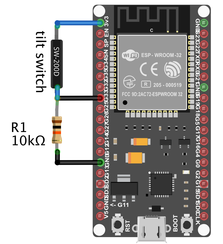
Poniżej kod. Żeby było trudniej piny budzenia to GPIO4 i GPIO15. Maska przyjmuje wartość 0x8010. Do pinu 4 podłączyłem czujnik przechyłu, do pinu 15 mikrofalowy czujnik ruchu. Oba świetnie wybudzają.
KOD
/*
Deep Sleep with External Wake Up
=====================================
This code displays how to use deep sleep with
an external trigger as a wake up source and how
to store data in RTC memory to use it over reboots

This code is under Public Domain License.

Hardware Connections
======================
Push Button to GPIO 33 pulled down with a 10K Ohm
resistor

NOTE:
======
Only RTC IO can be used as a source for external wake
source. They are pins: 0,2,4,12-15,25-27,32-39.

Author:
Pranav Cherukupalli <cherukupallip@gmail.com>
*/

#define LED_BUILTIN 2

#define PIN_BITMASK 0x8010 // GPIOs 4 and 15
//#define PIN_BITMASK 0x300000000000 // 2^33+2^34 in HEX

RTC_DATA_ATTR int bootCount = 0;

/*
Method to print the reason by which ESP32
has been awaken from sleep
*/
void print_wakeup_reason(){
  esp_sleep_wakeup_cause_t wakeup_reason;

  wakeup_reason = esp_sleep_get_wakeup_cause();

  switch(wakeup_reason)
  {
    case ESP_SLEEP_WAKEUP_EXT0 : Serial.println("Wakeup caused by external signal using RTC_IO"); break;
    case ESP_SLEEP_WAKEUP_EXT1 : Serial.println("Wakeup caused by external signal using RTC_CNTL"); break;
    case ESP_SLEEP_WAKEUP_TIMER : Serial.println("Wakeup caused by timer"); break;
    case ESP_SLEEP_WAKEUP_TOUCHPAD : Serial.println("Wakeup caused by touchpad"); break;
    case ESP_SLEEP_WAKEUP_ULP : Serial.println("Wakeup caused by ULP program"); break;
    default : Serial.printf("Wakeup was not caused by deep sleep: %d\n",wakeup_reason); break;
  }
}

/*
Method to print the GPIO that triggered the wakeup
*/
void print_GPIO_wake_up(){
  int GPIO_reason = esp_sleep_get_ext1_wakeup_status();
  Serial.print("GPIO that triggered the wake up: GPIO ");
  Serial.println((log(GPIO_reason))/log(2), 0);
}

void setup(){
  Serial.begin(115200);
  delay(1000); //Take some time to open up the Serial Monitor
  pinMode(LED_BUILTIN, OUTPUT);
  //Increment boot number and print it every reboot
  ++bootCount;
  Serial.println("Boot number: " + String(bootCount));

  //Print the wakeup reason for ESP32
  print_wakeup_reason();

  //Print the GPIO used to wake up
  print_GPIO_wake_up();

  /*
  First we configure the wake up source
  We set our ESP32 to wake up for an external trigger.
  There are two types for ESP32, ext0 and ext1 .
  ext0 uses RTC_IO to wakeup thus requires RTC peripherals
  to be on while ext1 uses RTC Controller so doesnt need
  peripherals to be powered on.
  Note that using internal pullups/pulldowns also requires
  RTC peripherals to be turned on.
  */
  //esp_deep_sleep_enable_ext0_wakeup(GPIO_NUM_15,1); //1 = High, 0 = Low

  //If you were to use ext1, you would use it like
  esp_sleep_enable_ext1_wakeup(PIN_BITMASK,ESP_EXT1_WAKEUP_ANY_HIGH);

  //Go to sleep now
  Serial.println("Going to sleep now");
  digitalWrite(2, HIGH);
  delay(3000);
  digitalWrite(2, LOW);
  esp_deep_sleep_start();
  Serial.println("This will never be printed");
}

void loop(){
  //This is not going to be called
}